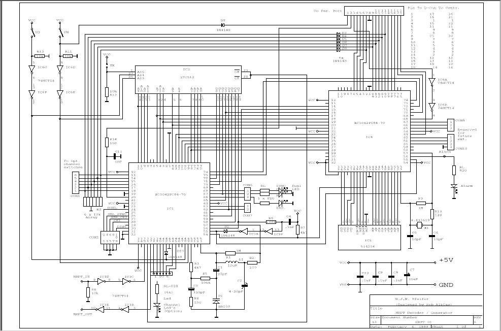
New HRPT/PDUS dcoder print
This new PCB is a bit more easy to build compared to the old one:
- Just one wireset between parallel port and PCB
- Some jumpers for old features removed
- Automatic reload of EPROM content while switching between HRPT and PDUS
If you do already have a "old" PCB don't worry; this one is still fine!
(The automatic reload feature is easy to add.)
The old web page with all info about this "old" design is avialable
HERE.
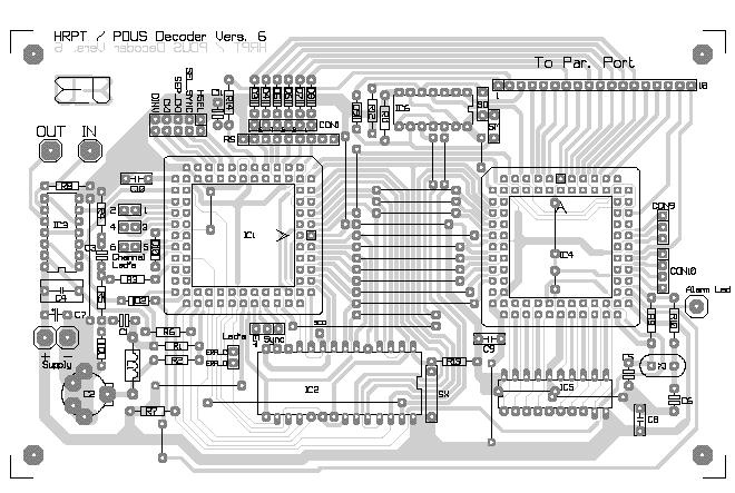
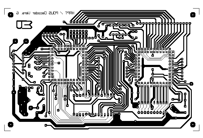
Print lay-out decoder.
Pushing FPGA's into their sockets sometimes needs some force. Removing them without damaging them or the sockets can be difficult without proper tools.
Make sure that you push the FPGA's in the right way into their sockets.
But first read Put into use.
Jumpers and connections.
| Jumpers (CON2) |
Only jumper 1-2 (HSEL) needed |
| SD (select HRPT/PDUS) |
HRPT: Open.
PDUS: Close. |
| SM (select decoder/generator) |
Not needed (selection is done via PC) |
| SX |
512k EPROM: Open.
256k EPROM: Close. |
Channel selection with switches.
Channel selection is done by the software. This is important because
the info about which channels are recorded is needed to reproduce the pictures.
This info is, therefore, saved in the file together with the picture.
If you want to select channels by means of swithes this is possible by adding 6 switches to CON1, and by removing jumper HSEL (CON2, 1-2), and by removing the diodes D3-D8.
Switch between decoder and generator.
Switching between decoder and generator is also possible by software. You don't need SM.
If you want to use a switch, add SM, and remove diode D9.
PCB info.
The print is designed by W. Pfeifer. The GIF-pictures are here to get an idea of the print layout. Resolution is, however, far too low to use it as a mask.
Use the PDF or the postscript file instead.