The hardware (1995 design).
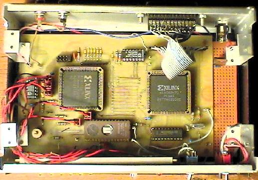
This is the decoder/generator hardware for HRPT, CHRPT and HRI (note: no HRI after december 2005!)
- The 2 square IC's are the FPGA's.
- Left-below, on PCB the trimmer to adjust the central VCO frequency
- Right-below left-FPGA: EPROM containing the decoder and generator codes
- Below right-FPGA: The elastic-store DRAM and XTAL, for the DRAM controller (which is in this FPGA)
- Top (back panel), left: connectors for HRPT-input (from receiver) and output
right from middle: output to PC parallel port.
- Bottom, against front panel: PCB with LEDs; switches for decoder choice, power switch
between EPROM and RAM module: Dip switch. Just 2 switches are used,
to select between HRPT, CHRPT and PDUS. (Selection between decoders and generators is done via the parallel port.) This dip-switch is replaced by connectors/jumpers on the new PCB.
At the left the trimmer to adjust the VCO frequency.