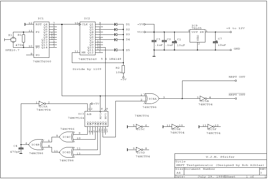
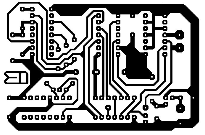
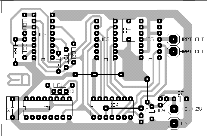
Schematics and PCB lay-out of a simple HRPT henerator.
Updated 31-8-1999.
In the previous version IC9 was wrongly connected. If
you have already made a old PCB, you can use it, but make sure that you
insert IC9 in the correct way!
You can change it into a CHRPT generator by using a Xtal of 21.4 MHz
instead of the SFE10.7.
Instead, you can use a LC filter (L instead
of X1, 1 capacitor from one side of the L to ground, a trimmer from the
other side to ground):
- HRPT (10.6464 MHz): L=12uH, C=39pF, trimmer=10pF
- CHRPT (21.2928 MHz): Add second L of 4.7uH parallel to the 12uH one
With the 2 coils you can easily switch between HRPT and CHRPT.
Best is to check the frequency by measuring on pin 7 of IC1; this should be 665.4 kHz for HRPT and 1330.8 kHz in case of CHRPT.
(You have to play a bit with C and/or L; parasitics have noticable influence. Normally, for CHRPT a L of 6 uH would be necessary, which means 2x 12uH in parallel, instead of 12uH // 4.7 uH!)
Postscript format schema.
PDF format schema.

Postscript format PCB copper side.
PDF format PCB copper side.
(Design: W. Pfeifer.)
NOTE: Scale is 1:1.414. Reduce 71% (A3 ==> A4). Picture is in reverse!
Use PDF or postscript files, NOT this GIF file to make your PCB!

Postscript format PCB component side.
PDF format PCB component side.


